
Guy Makes A Proper 4:3 Bartop Arcade Cabinet
Kenneth Coo
Published
11/29/2015
Anything is possible if you put your mind to it.
- List View
- Player View
- Grid View
Advertisement

-
1.
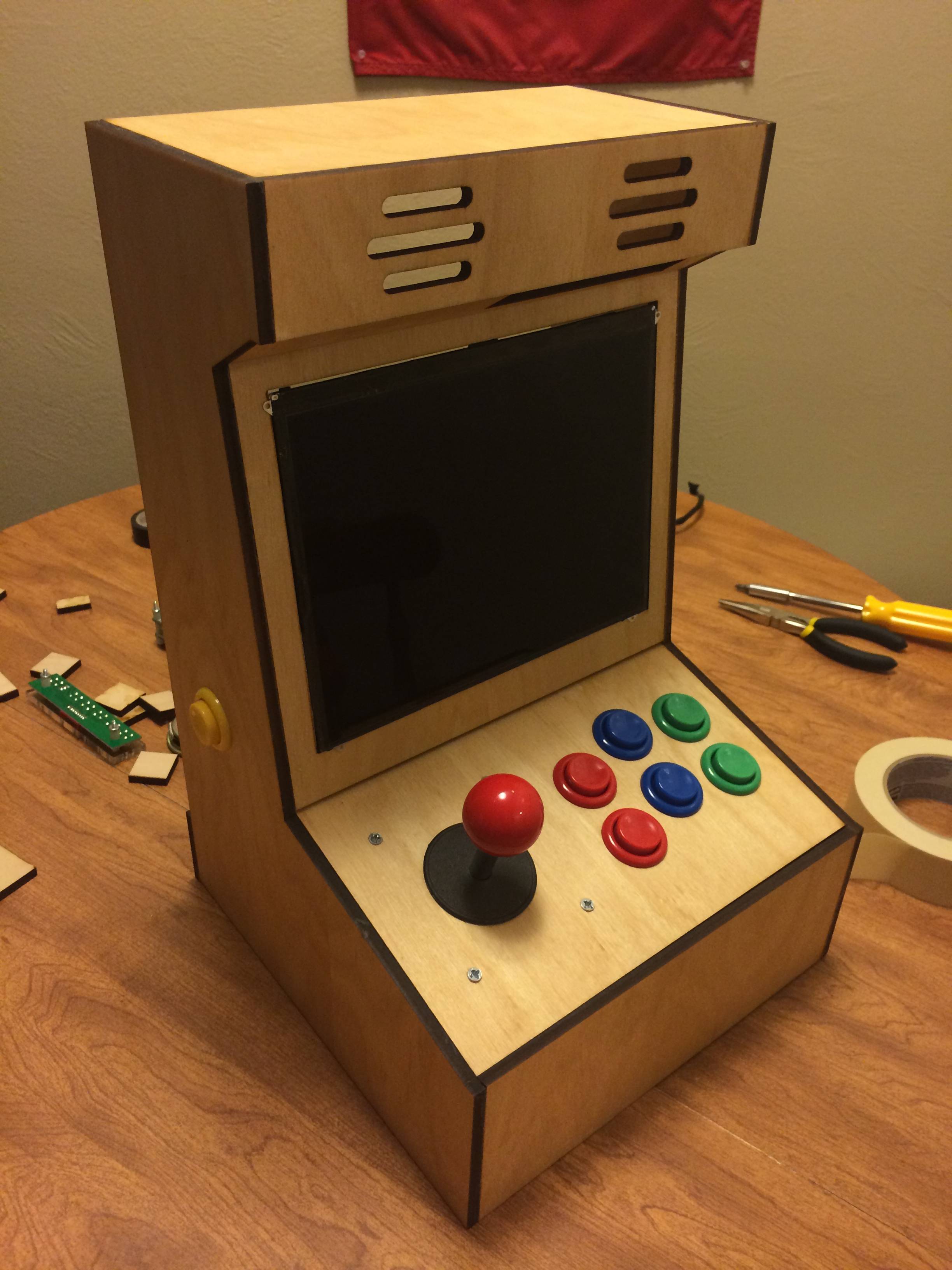
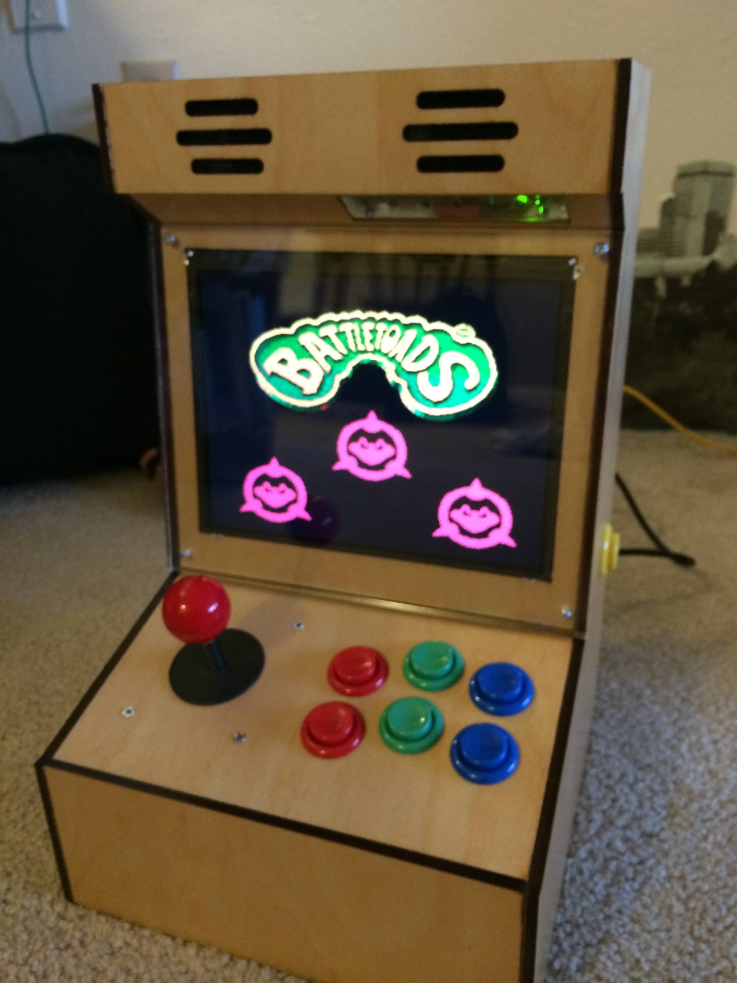
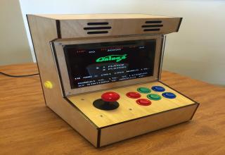
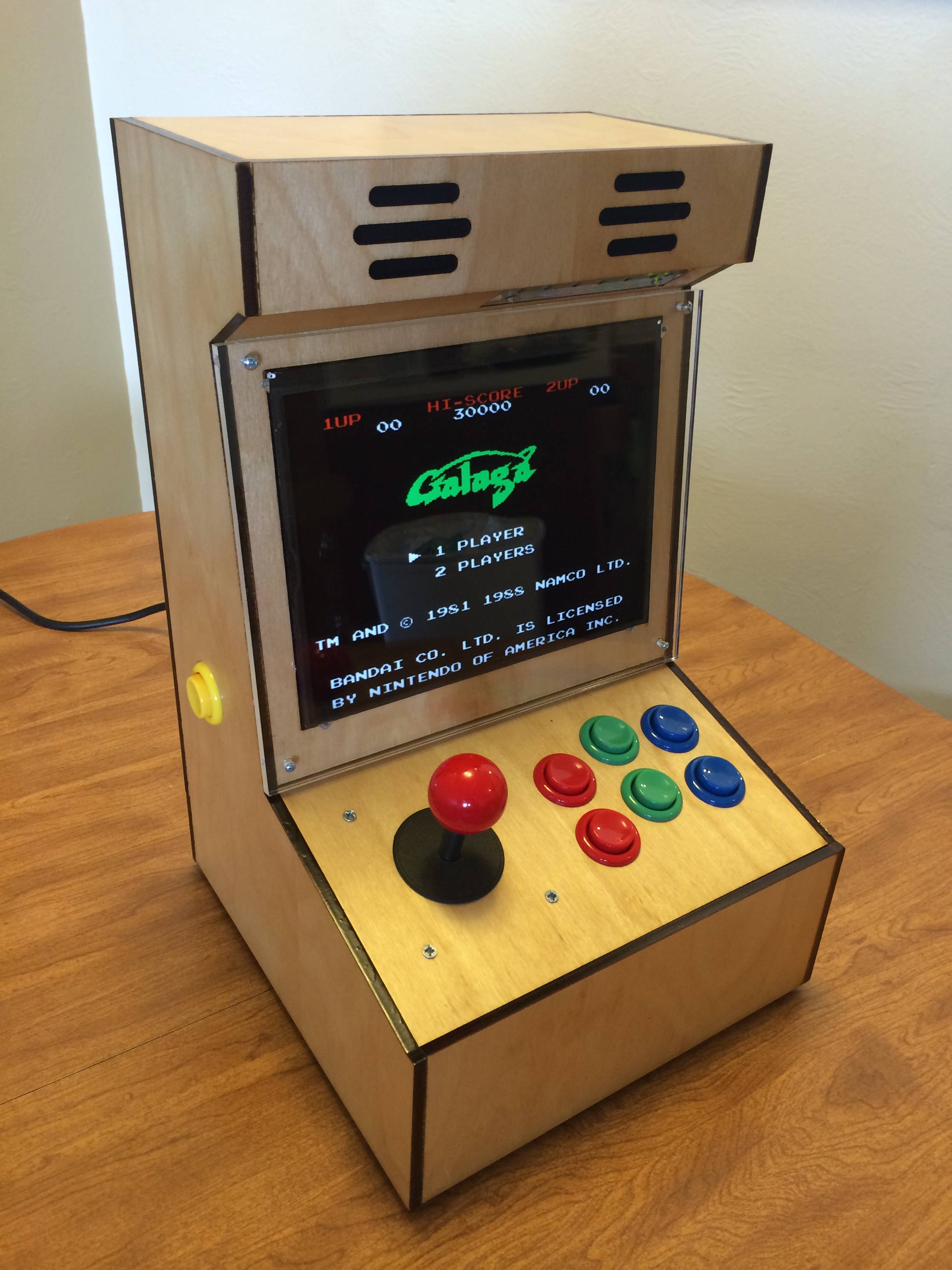 Finished picture first, running the NES version of Galaga.
 -
2.
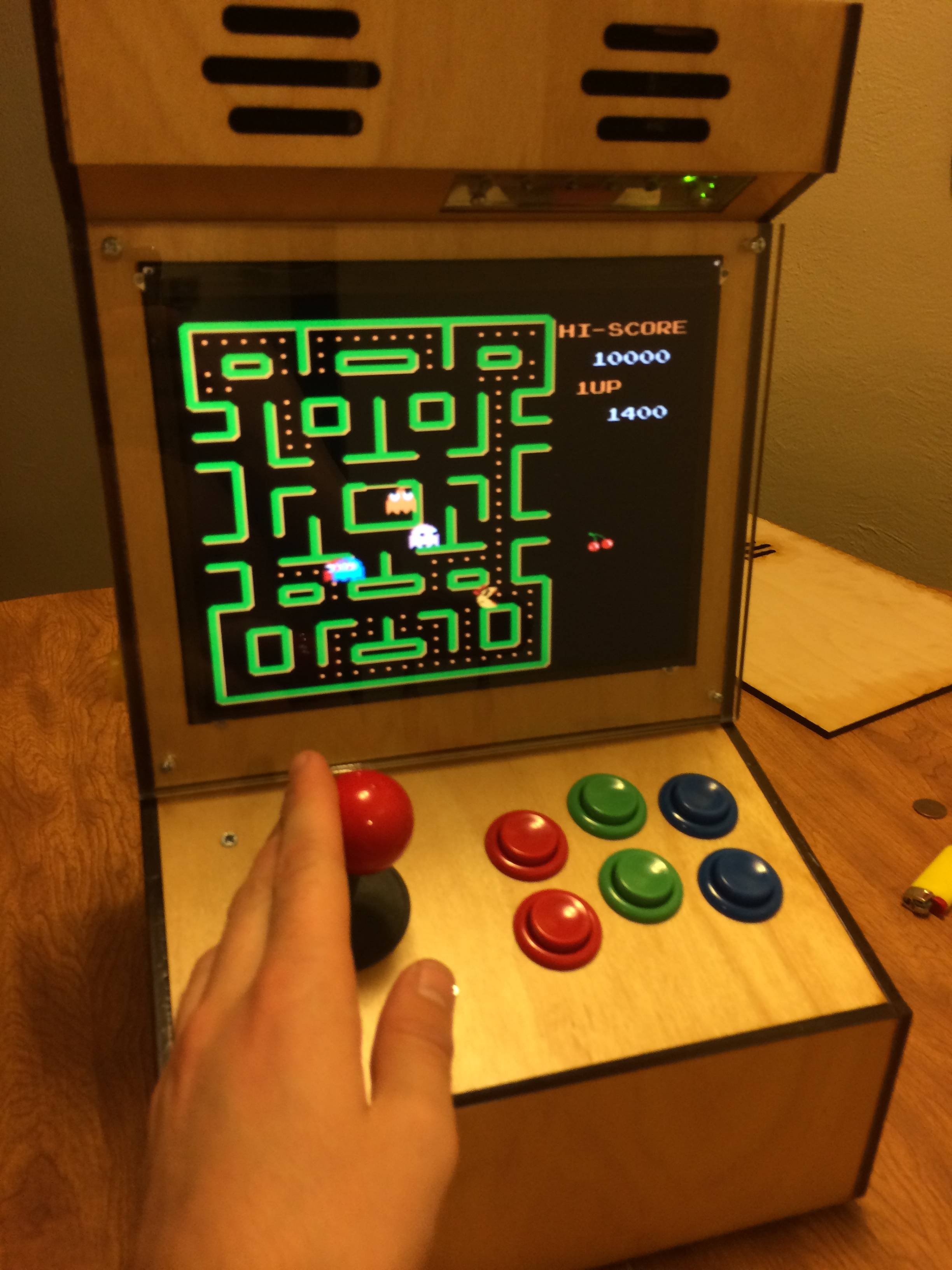
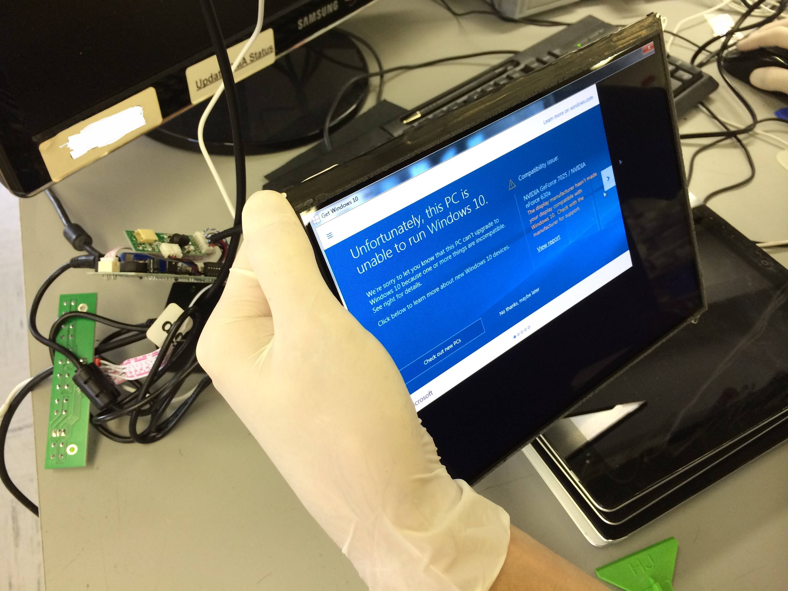 So I’ve seen a bunch of bartop arcade cabinets before, but they all had 16:9 screens. This always bugged me because the majority of the games I’m going to be playing on it are 4:3 and I’m an aspect ratio nerd. The iPad 2 LCD is 1024 X 768 and 10 inches and a 4:3 aspect ratio. perfect for what I was trying to do. Here I am testing the LCD driver board I got from China. I actually ordered an Ipad 1 LCD driver board, but the board would only work with the iPad 2 LCD. Whatever, at least it works!
 -
3.
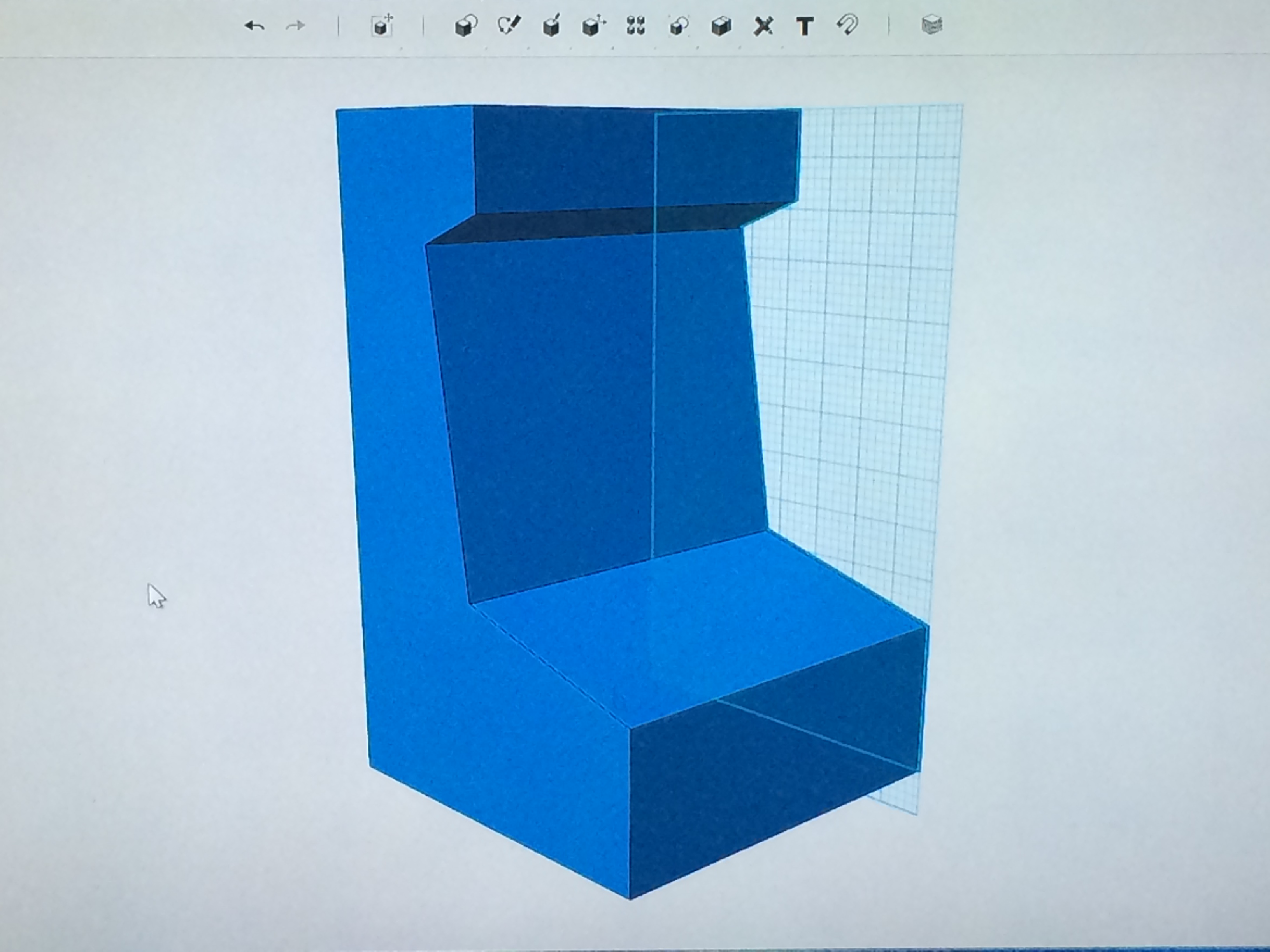 Here is a rough 3D sketch I did in autodesk 123D, free software that is pretty sweet. Mainly trying to get the side profile I wanted.
 -
4.
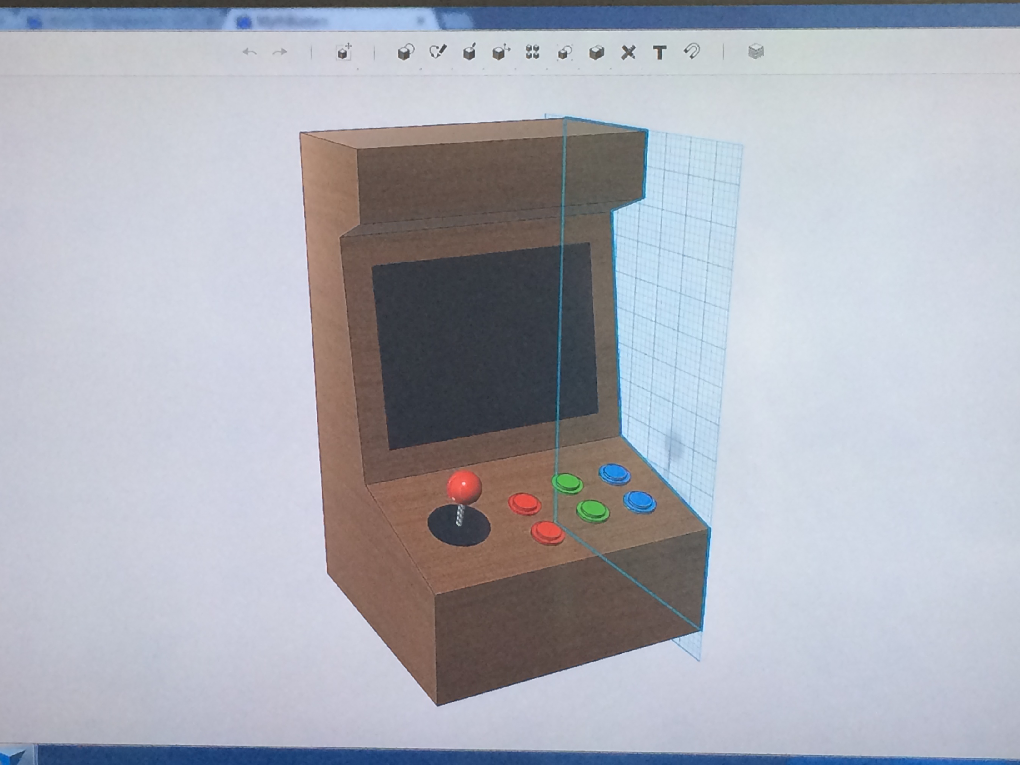 Added buttons, joystick and screen, just having fun and getting to know the software. A lot of this project was a huge learning experience for me.
 -
5.
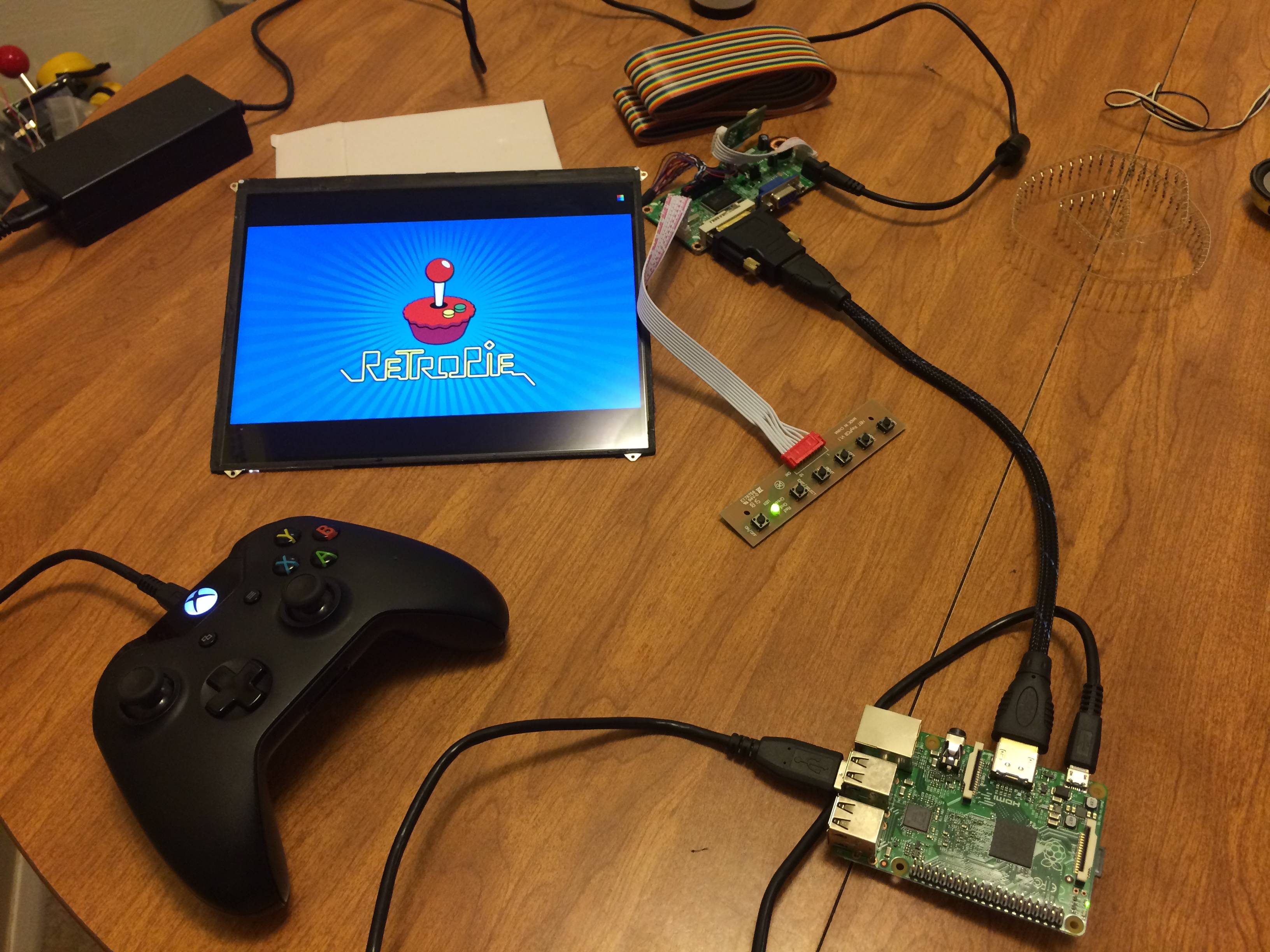 Got my new quad core raspberry pi in and had to test it out! Just wanted to poke around in RetroPie.
 -
6.
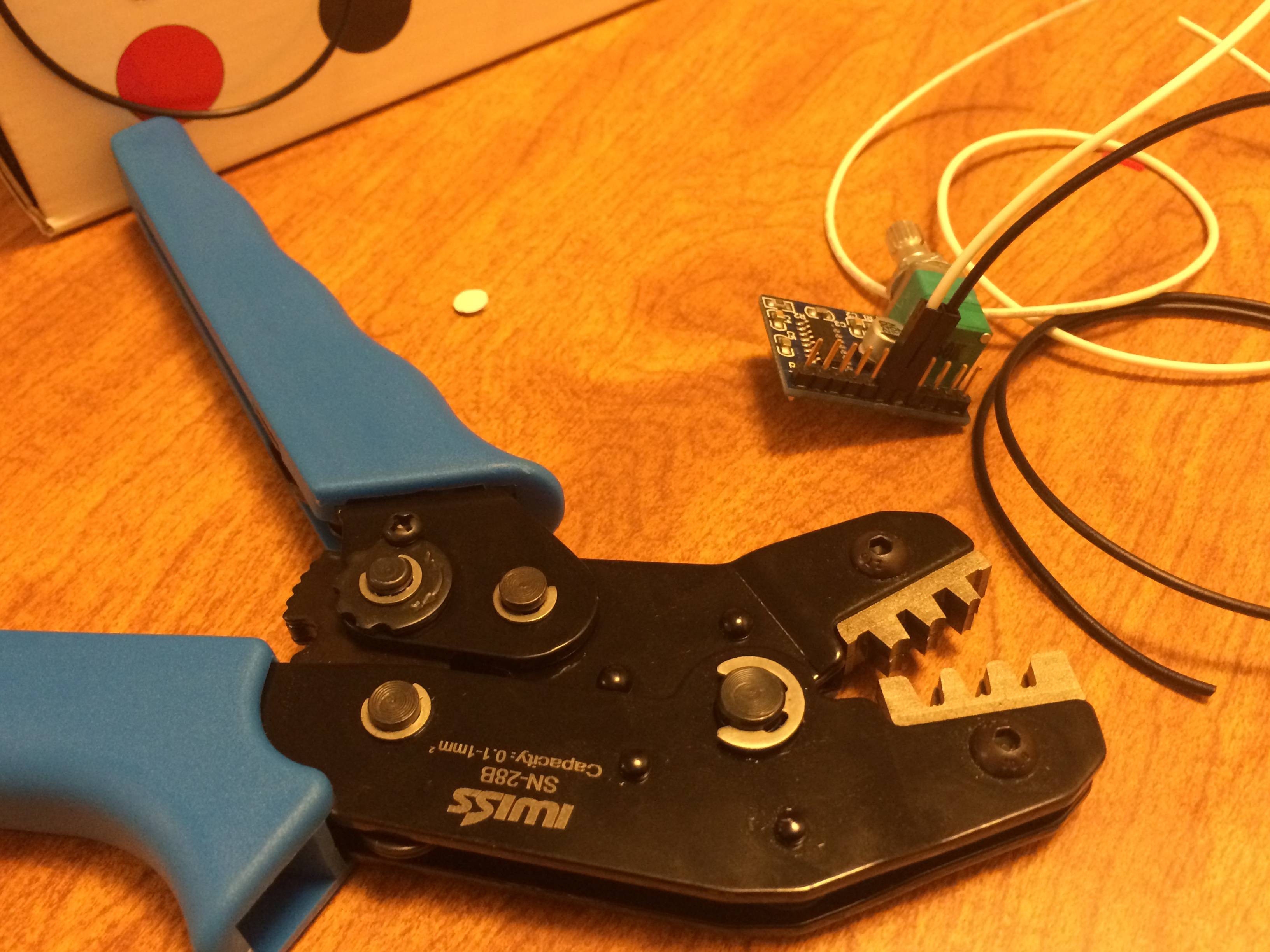 Here is my wire crimper I had to get and my tiny little audio amp.
 -
7.
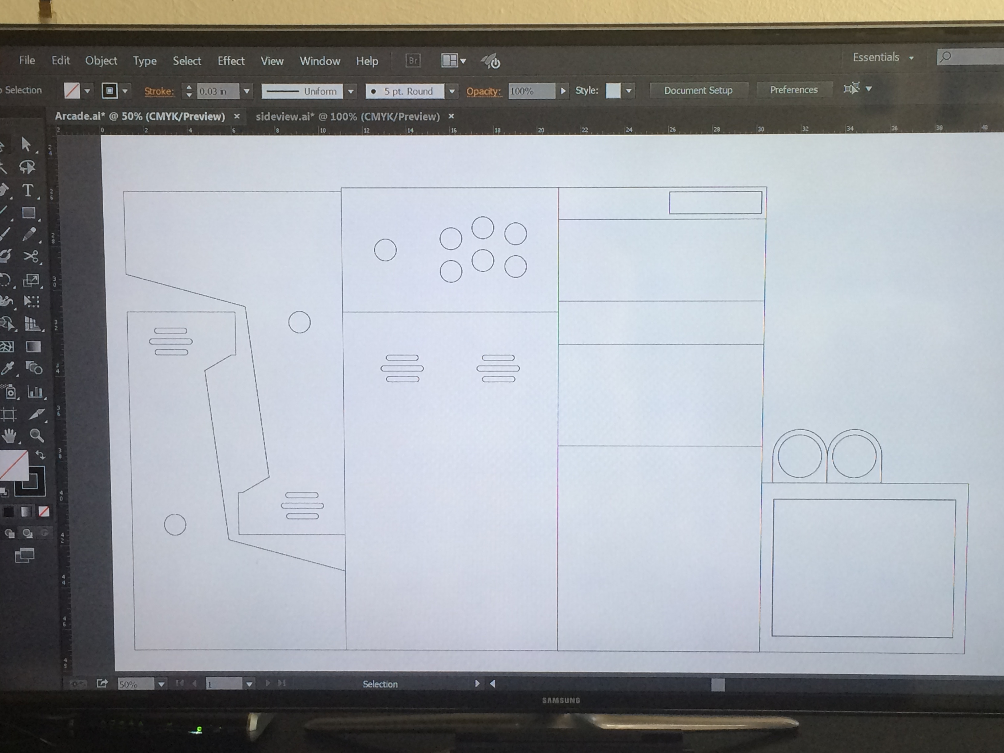 So here are my actual Laser Cut plans I drew up in illustrator. This part took a while to get right, triple measured everything before I finalized my design. I’ll post the .AI files somewhere if you want to copy my project.
 -
8.
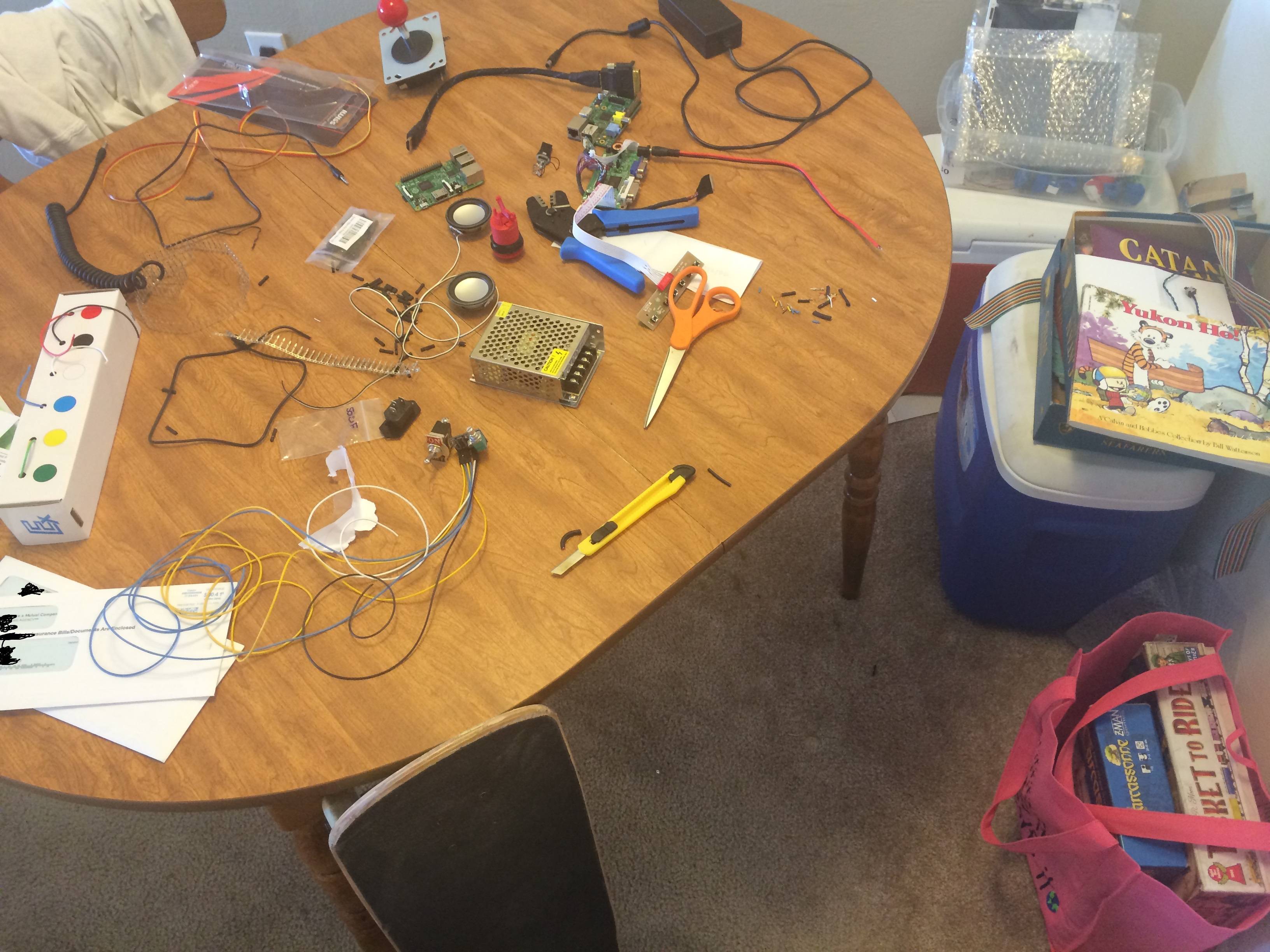 Parts just pouring in now. The SD card reader on my old raspberry pi broke. At this point I was trying to use an old aux cable, but ended up just making my own. Crimping or soldering those tiny wires is near impossible.
 -
9.
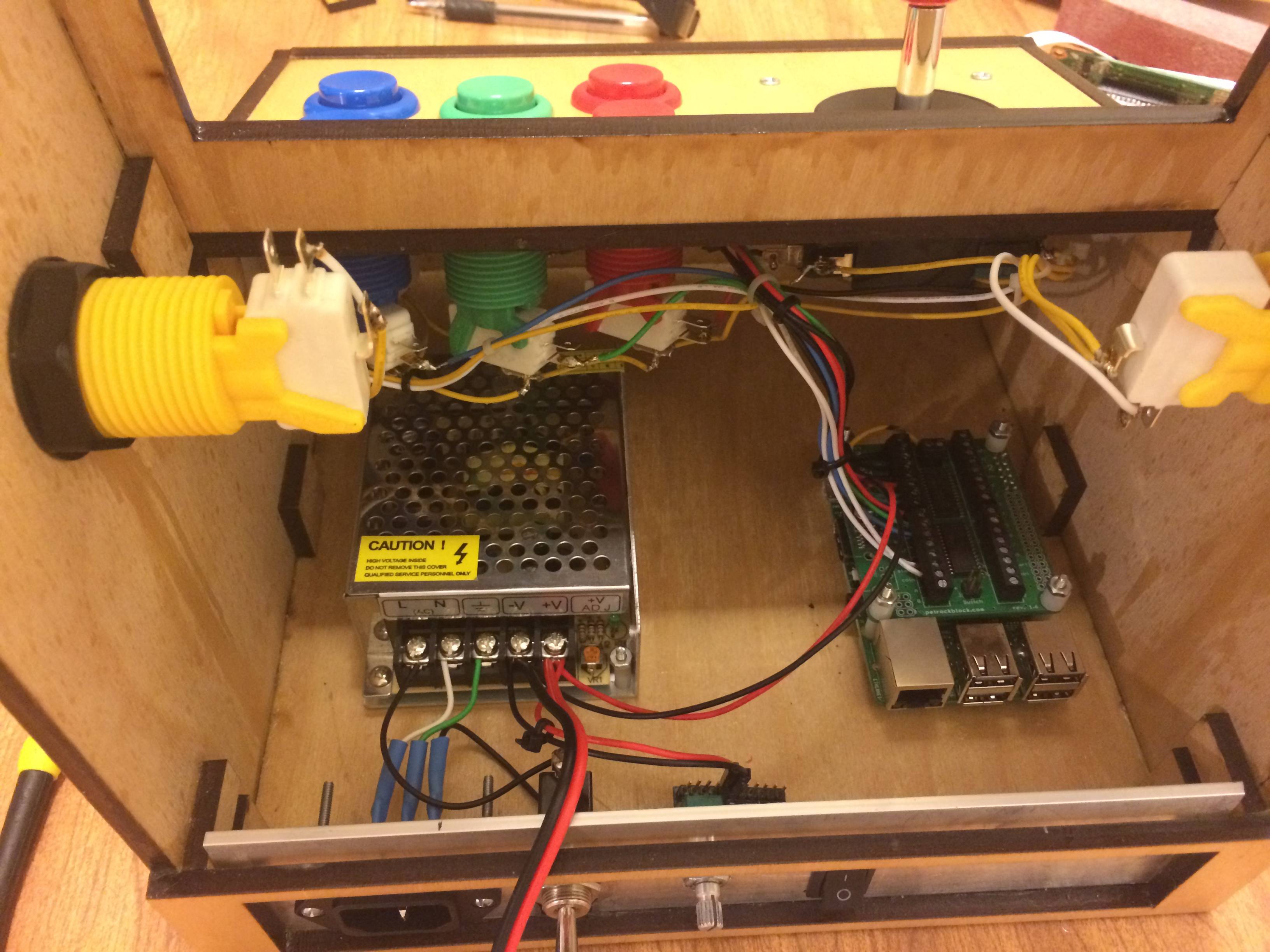
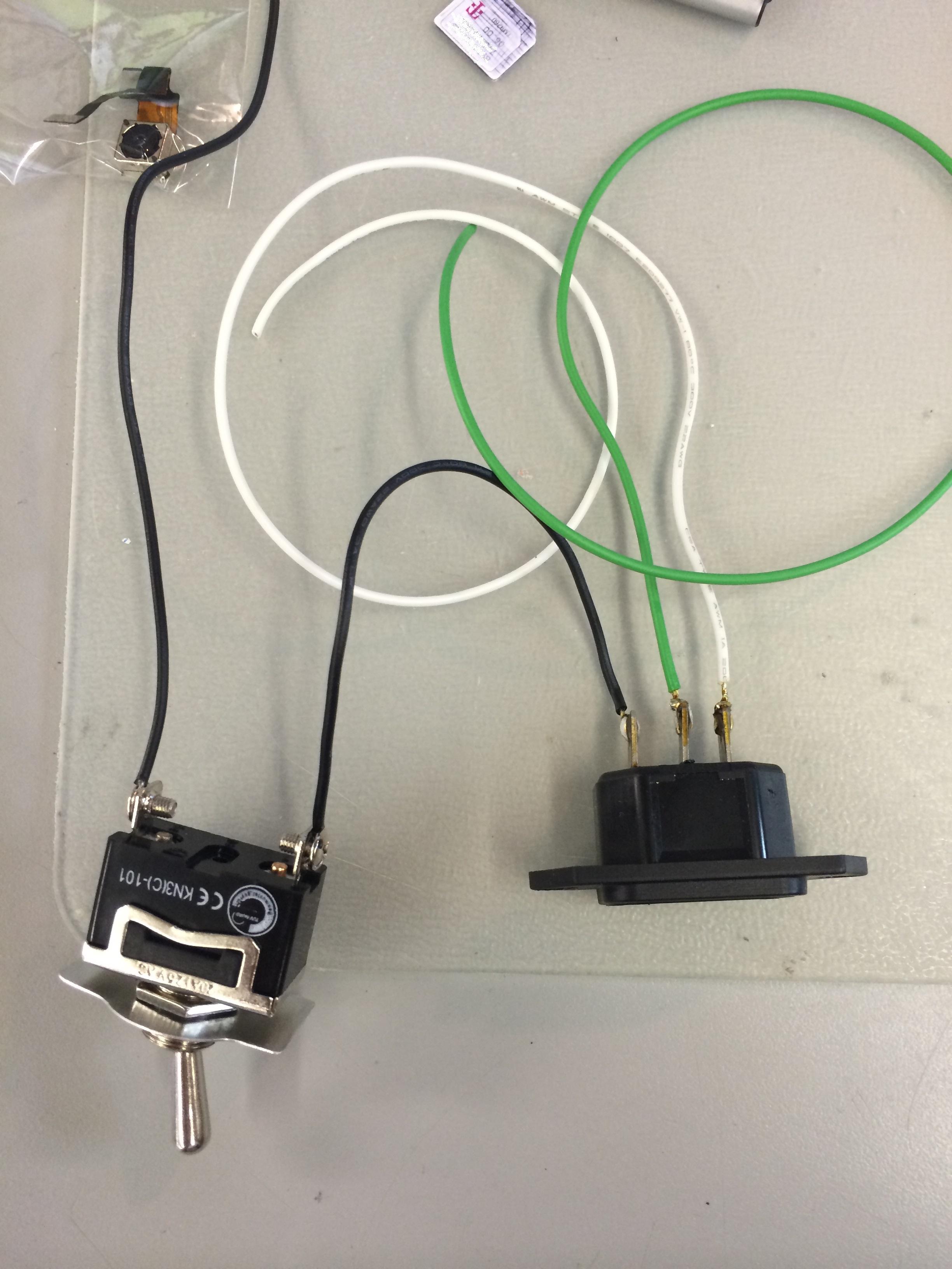 Here is my IEC socket I soldered, and it connected to the SPST Switch. My PSU was a 5v 5 amp 25 watt switching power supply.
 -
10.
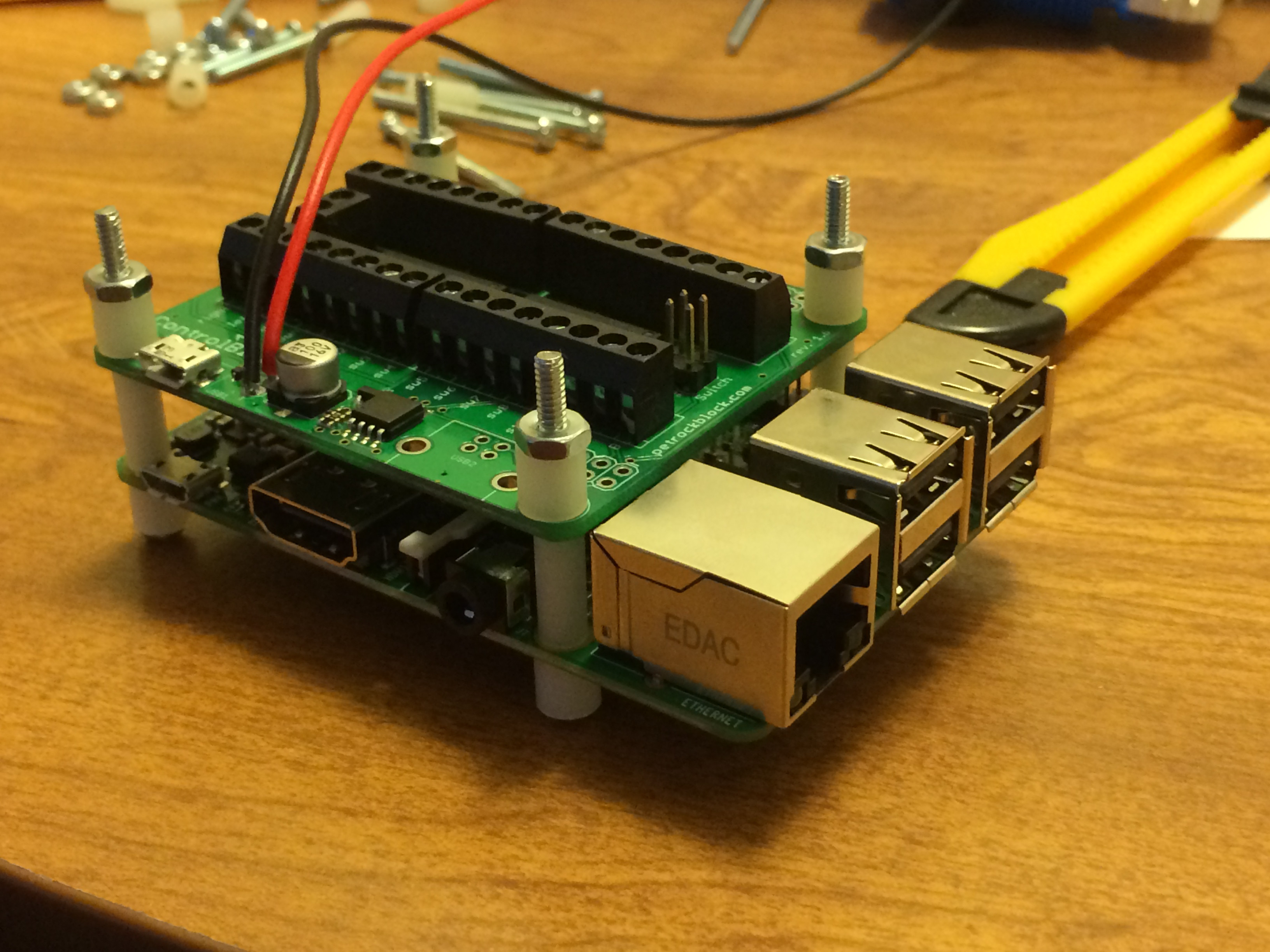 Here is the control block attached on top of the raspberry pi. There are some nylon spacers in between I picked up at Ace Hardware. Essentially, the top board ads 1)Place to solder 5V 2)input for all buttons 3)Power Switch for proper shutdown command so I don’t corrupt my SD card as easily.
 -
11.
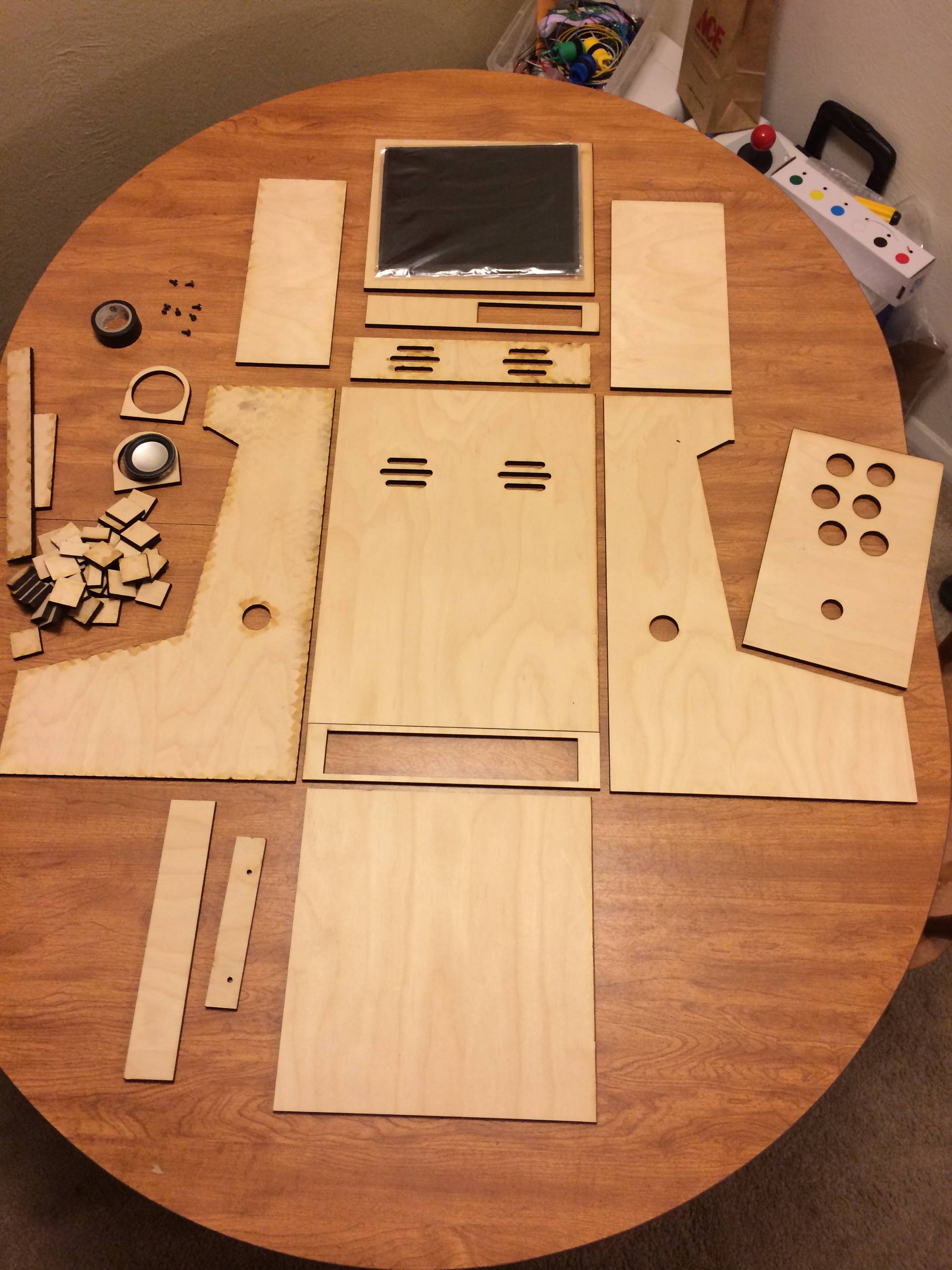 Okay finally! I’ve got something to put all this crap inside. I paid about 160 to have the wood and acrylic laser cut from a local business. The wood is ¼”, White Oak veneer, with an MDF Core. The machine left some burn marks on one side of the wood as you can see on the left, So one of the side panels had to be sanded down really good before I started finishing the wood.
 -
12.
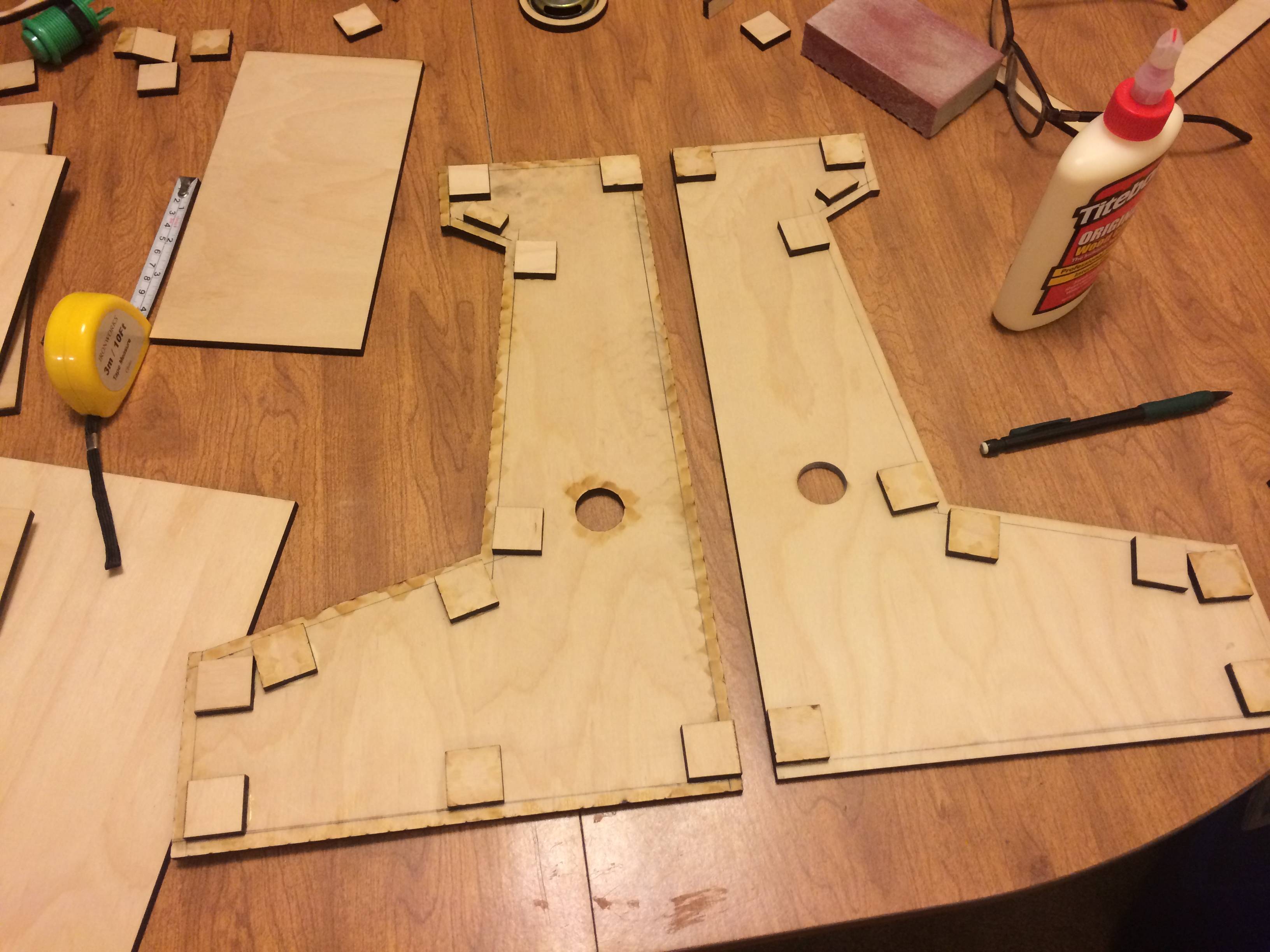 Here is how I made sure all the panels would sit flush. I had a bunch of 1X1 squares cut and used them as supports. When placing them down I had another piece of wood so that they would be exactly ¼ inch away from the edge. Ended up working perfect as all my joints are freaking sweeeet.
 -
13.
 Doing a dry fit to make sure everything fits. And it does!
 -
14.
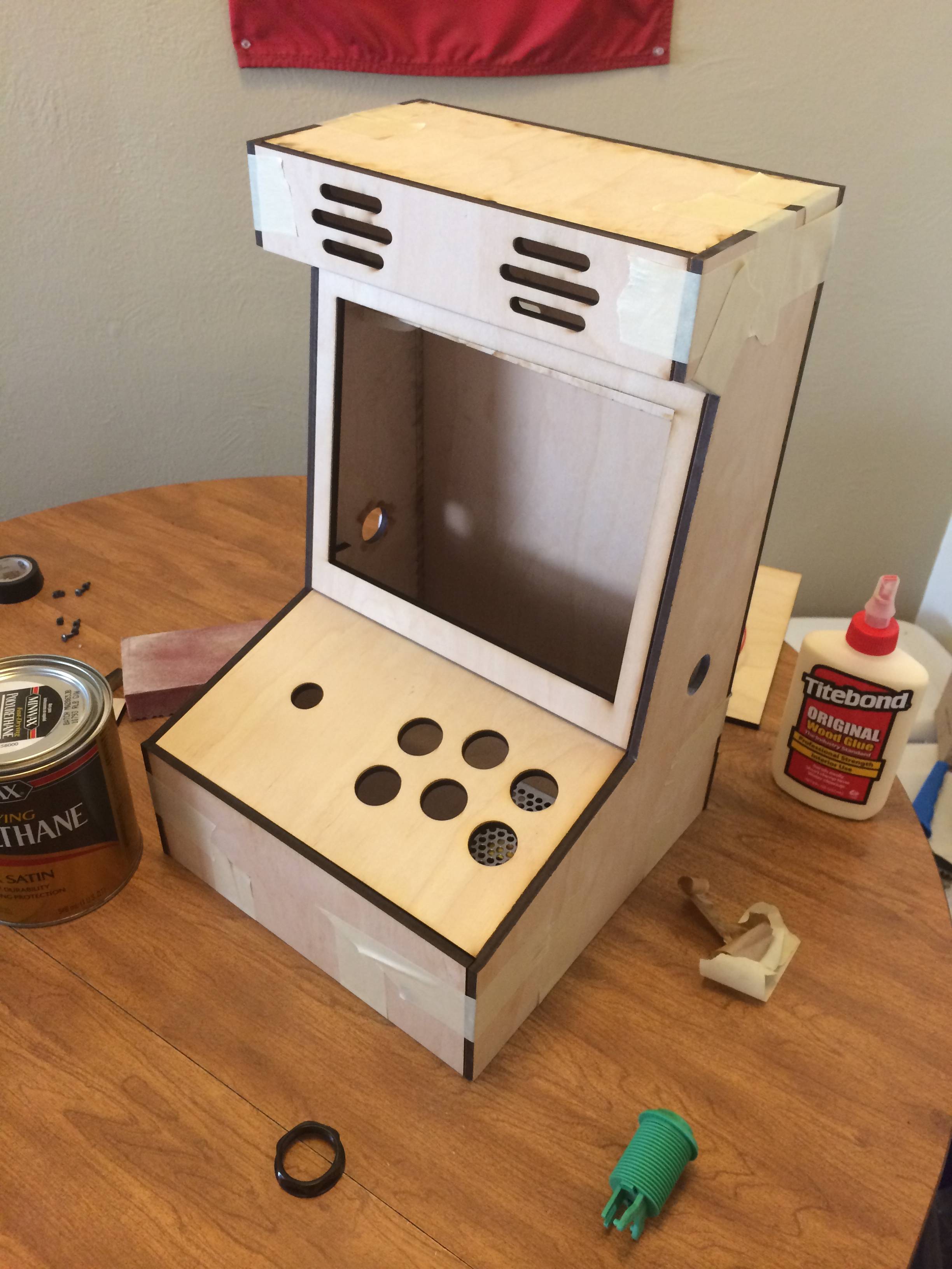
 The only problem I ran into with my laser cut designs is that I measured the buttons to be 1 inch, and they were 1 and 1/8th inch. A simple google could have solved this but, ehh whatever. So I took a drill bit and went counter clock wise on all the holes and made the buttons fit. Here it is all glued together though.
 -
15.
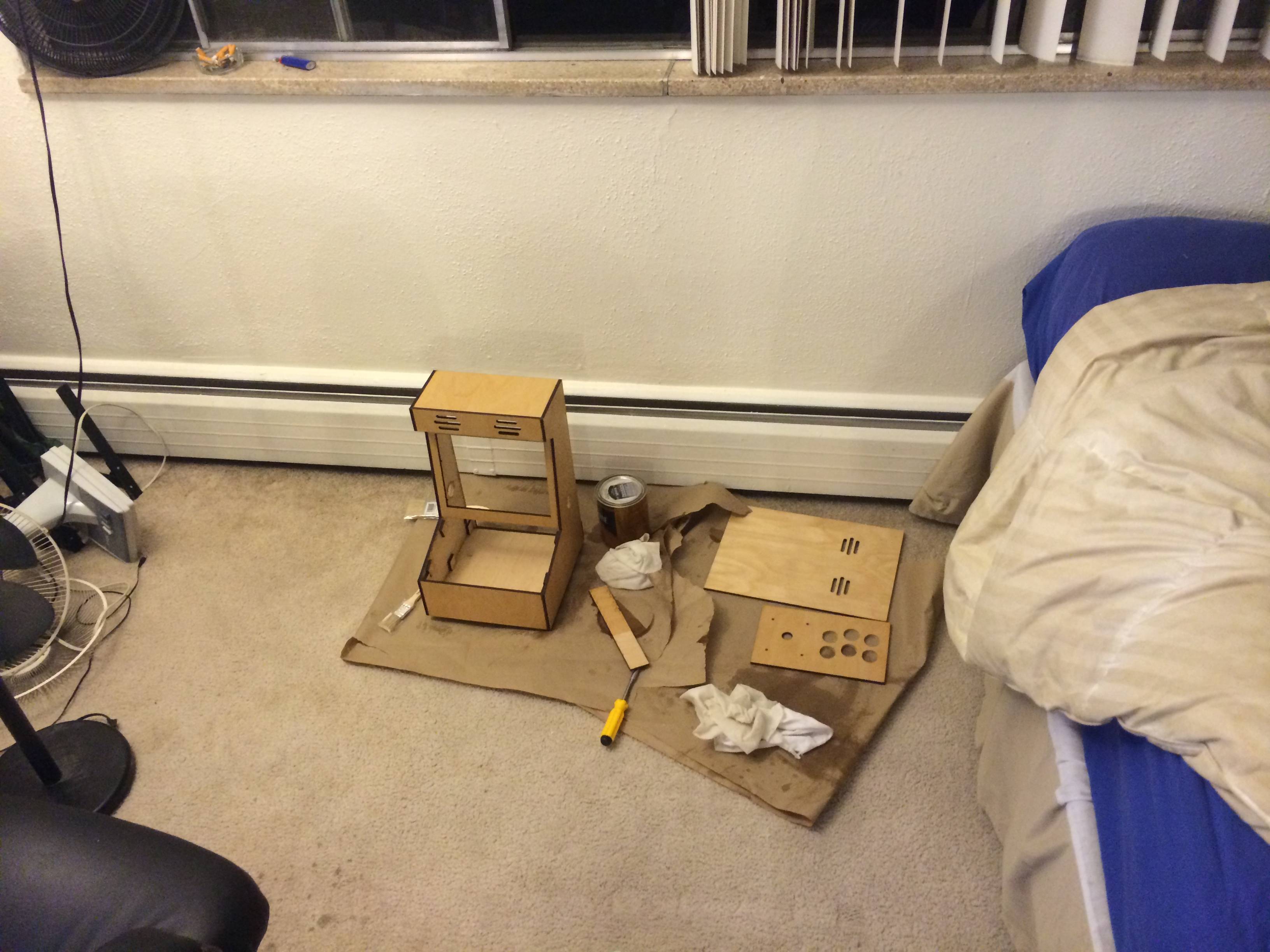 Here I am staining and finishing it in my apartment. I did 2 coats of Danish Oil, and then 3 layers of a satin polyurethane finish. I’m no expert in finishing wood, so its not perfect but I’m really happy with the way it came out.
 -
16.
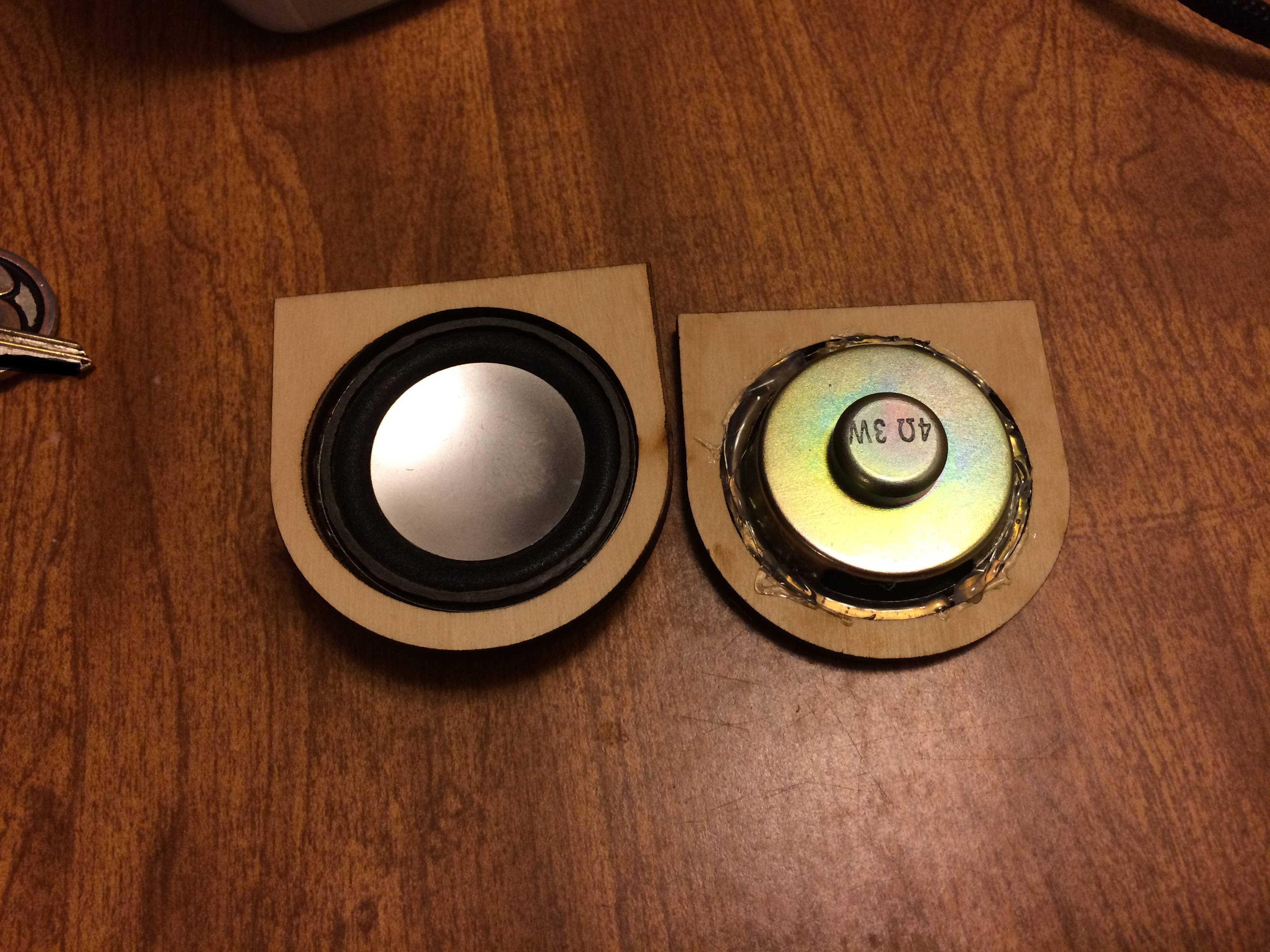 Here are the little circle things I had laser cut, and then hot glued the speakers into.
 -
17.
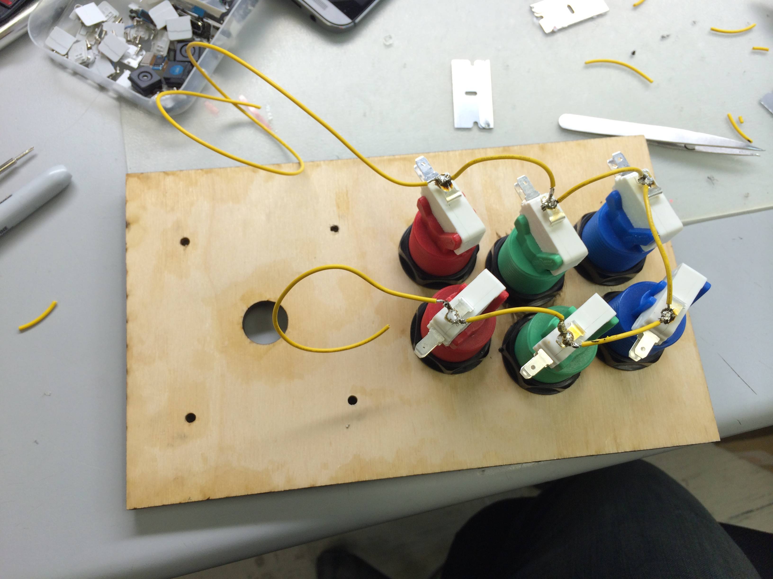 Starting to soldering the common/ground.
 -
18.
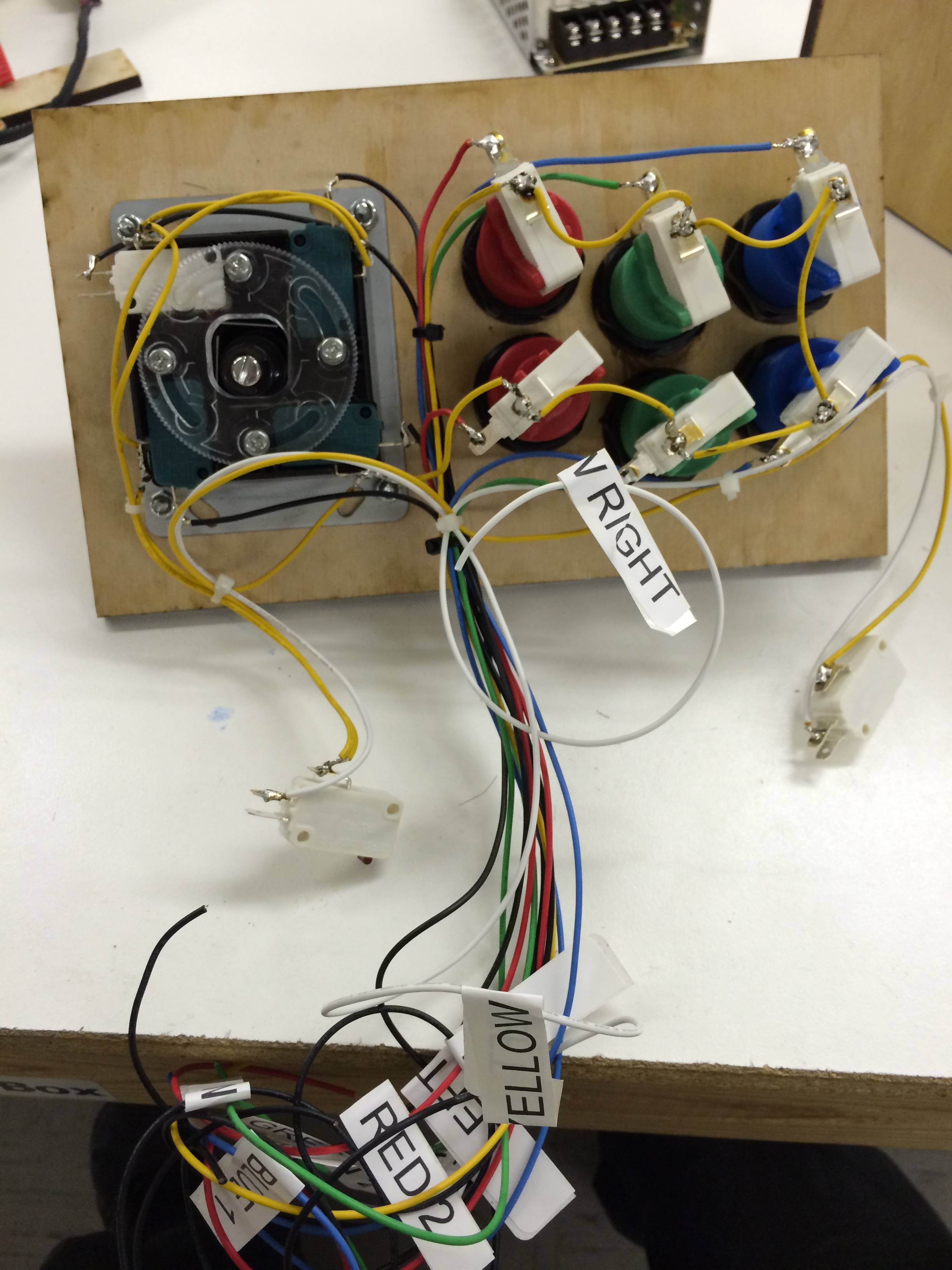 Majority of wiring done. I ended up breaking 3 of the buttons on the joystick while soldering because I got them too hot and the plastic melted. I didn't break any of the white switches though.
 -
19.
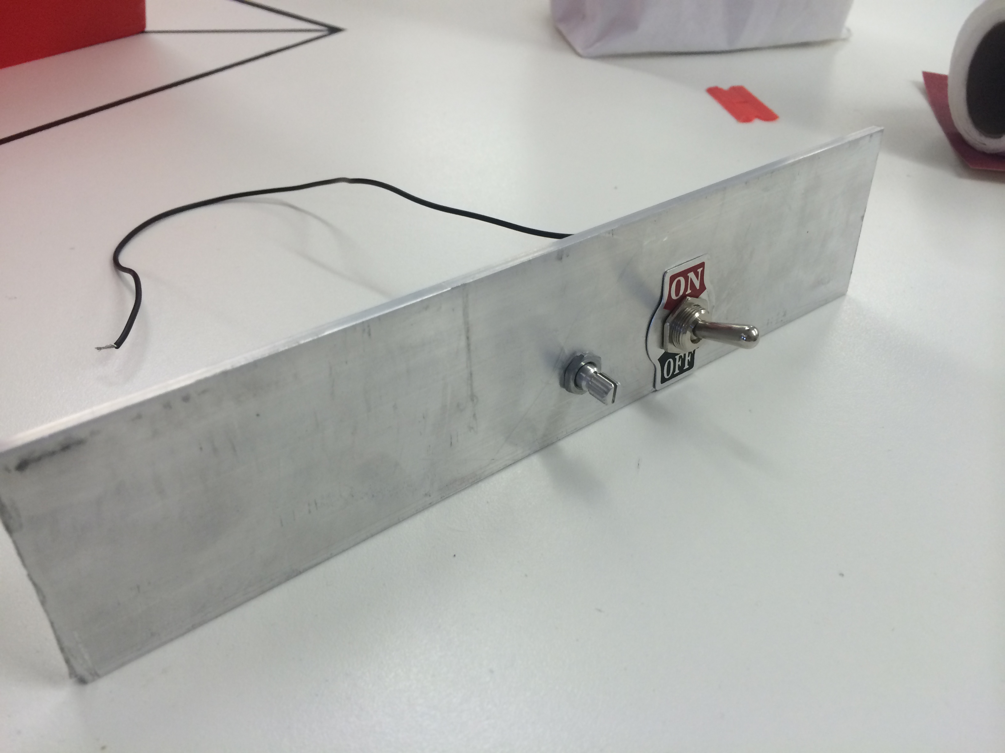 I got this hunk of 2” aluminum from home depot. Spent probably an hour and a half getting all the holes right. I was going to drill out a place for the ethernet/USB ports on the raspberry pi but I said “fuck that noise” after finishing up all the other IO. The aluminum was really thick.
 -
20.
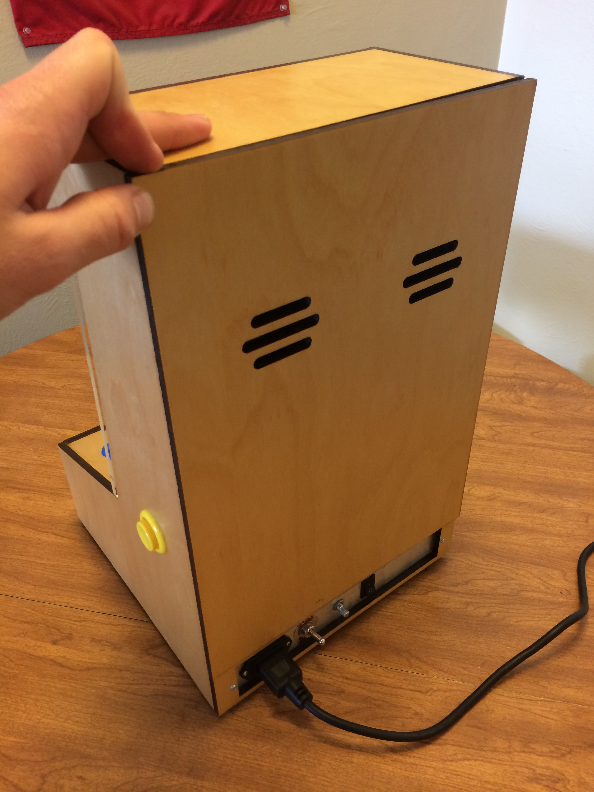
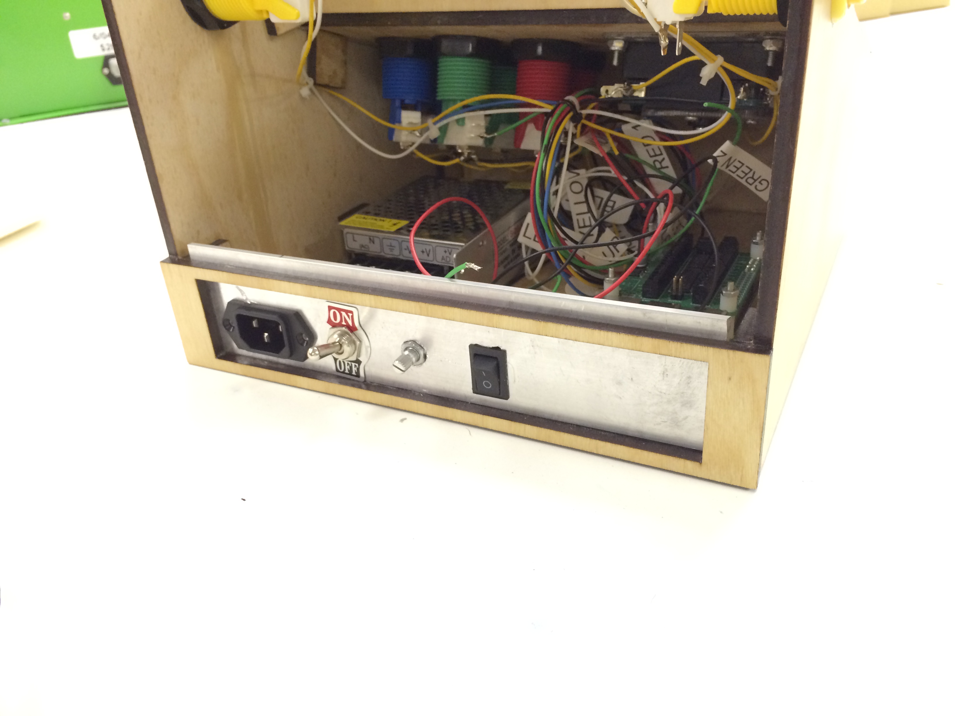 IEC, Power switch, volume knob and computer power switch installed. Also, if you do this, GROUND YOUR BACKPLATE IF ITS METAL! I was testing it out and heard a short somewhere (Snapping noise and then computer restarts). I grounded the backplate as an initial hunch and no more shorts! Luckily none of the components were damaged when I did short it out. . .
 -
21.
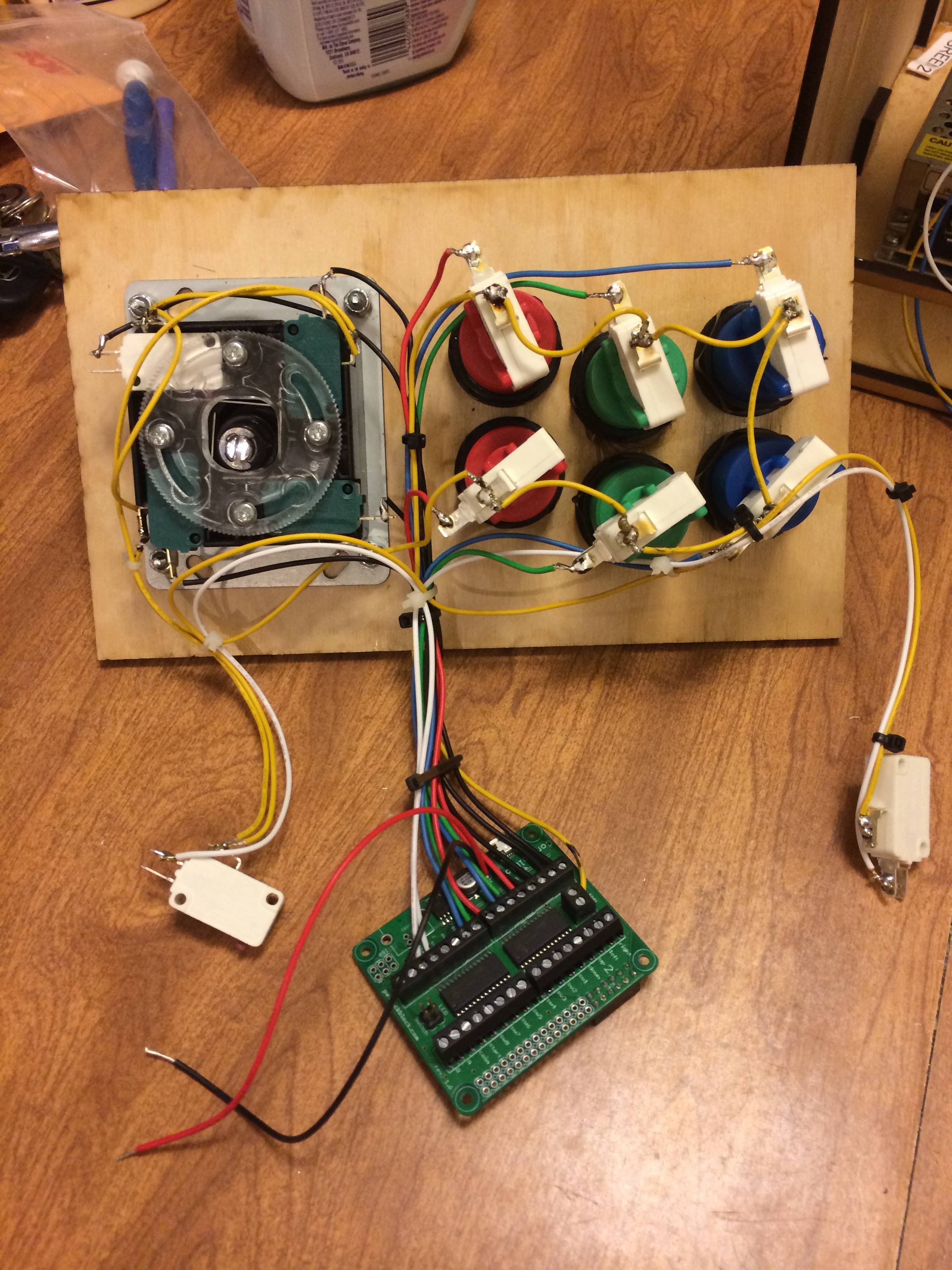 Here are all the buttons attached to the Control Block. You can also see the 5V black and red lines coming out of the Control Block.
 -
22.
 Starting to come together.
 -
23.
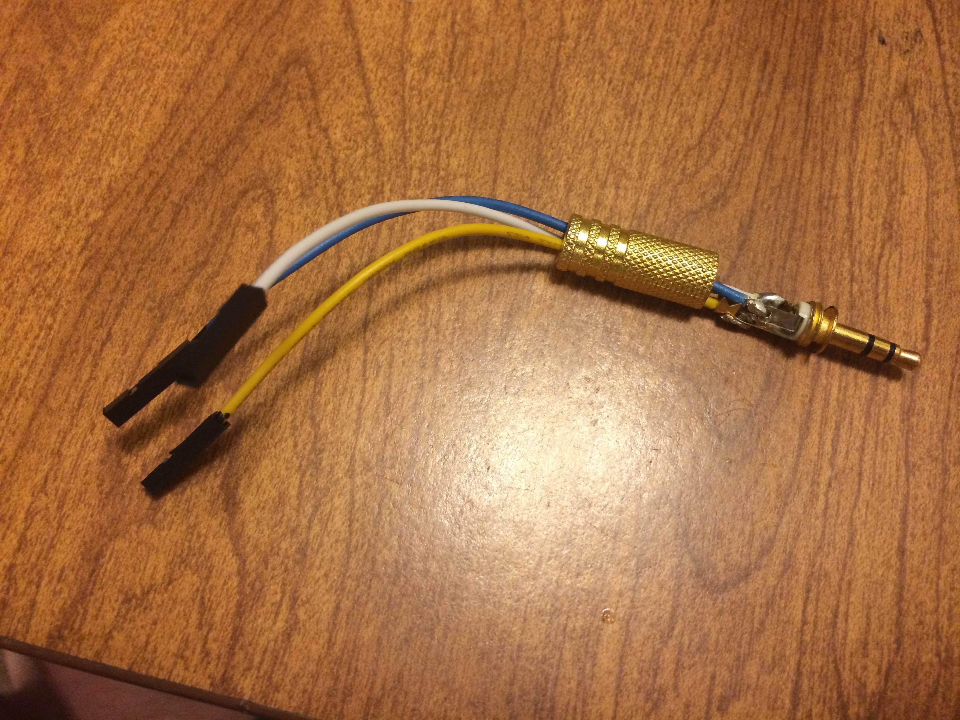 The cutest little audio cable you ever did see! Left it open so you could see how I soldered this. Also ended up fixing an old pair of headphones once I realized you can replace the 3.5mm part.
 -
24.
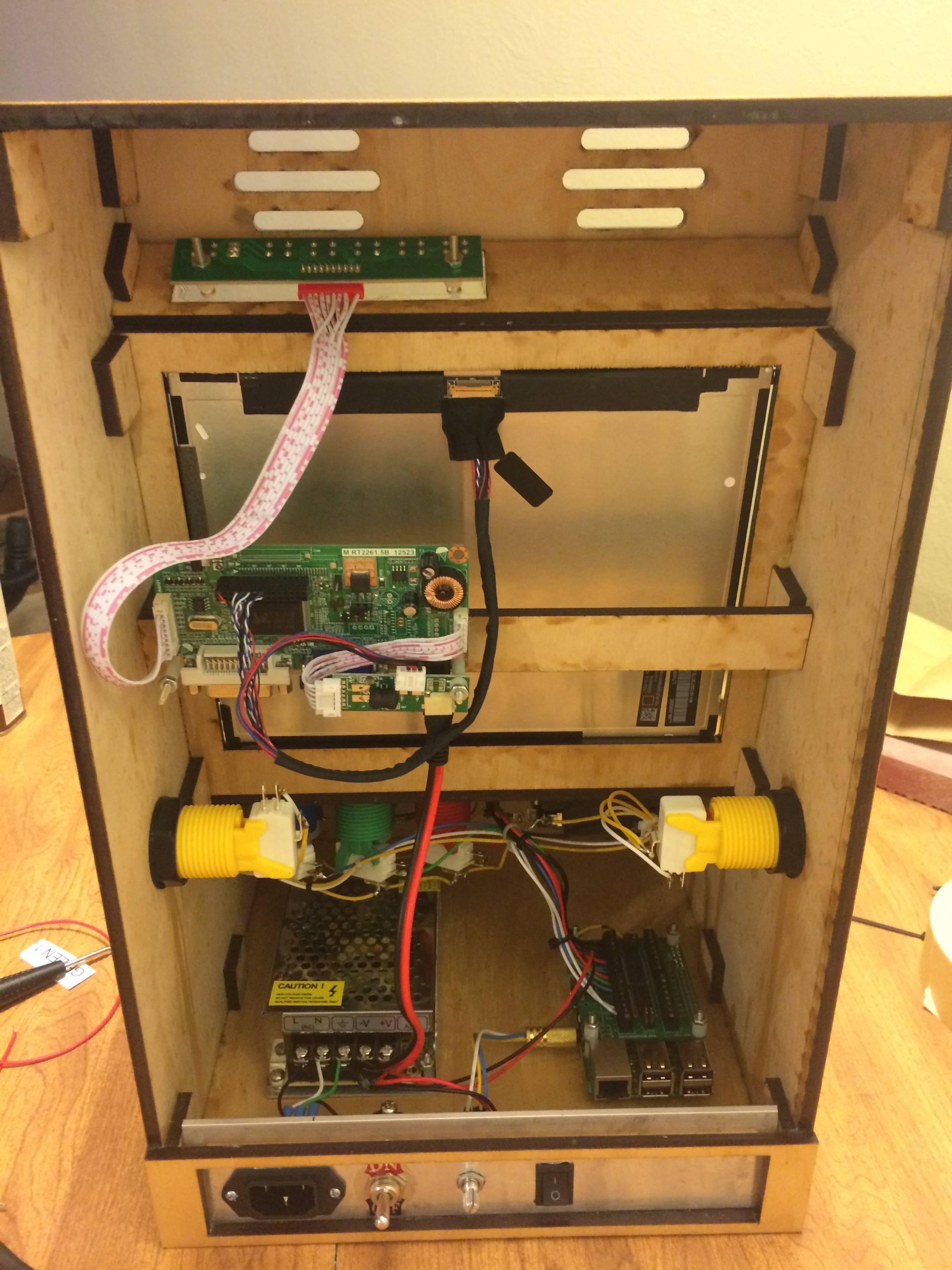 More stuff coming together, LCD driver board and input switcher thing mounted on the top. There's an LED that's green if it has a source to display and red when there is no source. Didn't functionally probably need it up there but it looks cool. And I was already paying for the acrylic to be cut so why not.
 -
25.
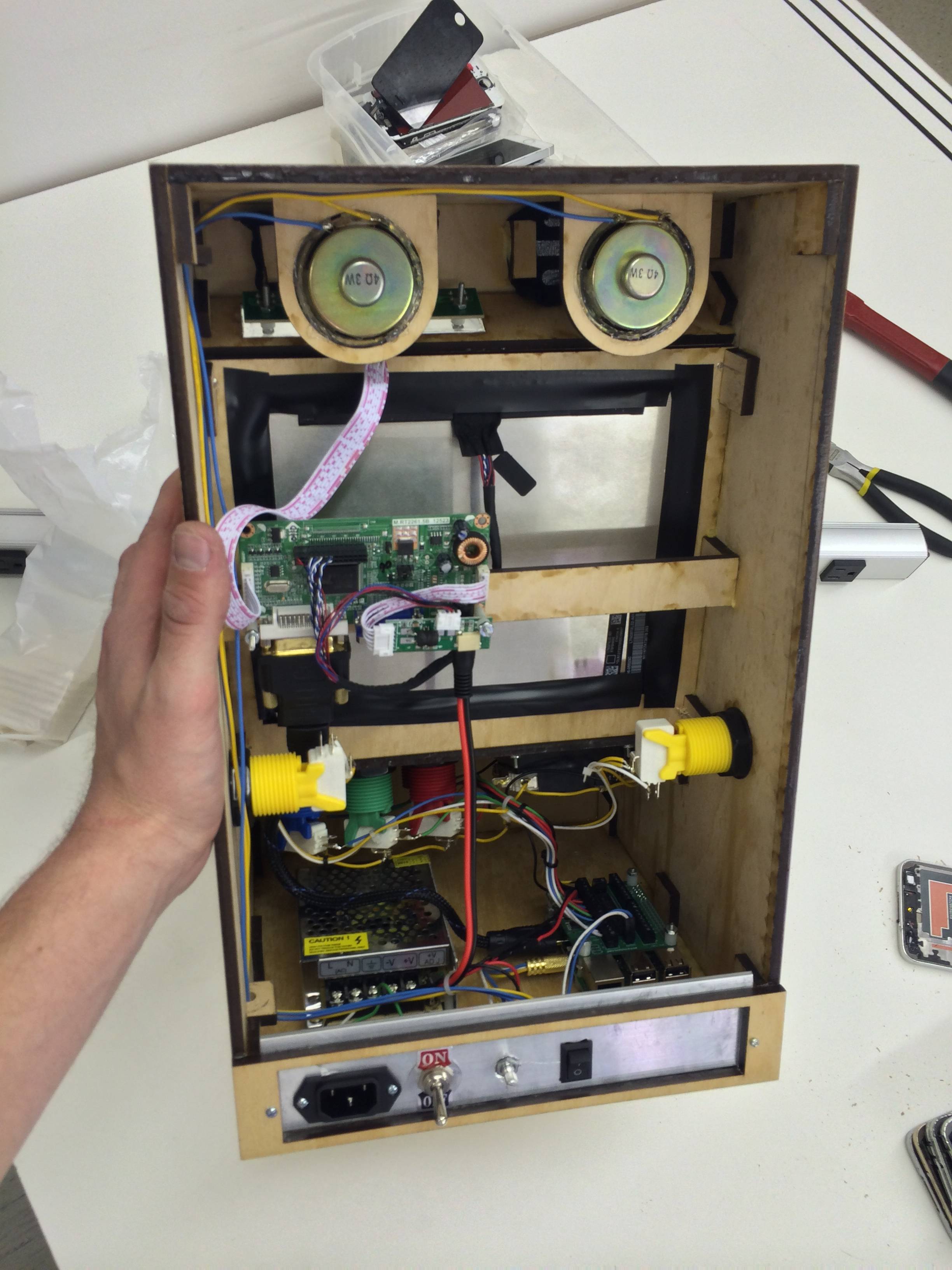 I installed a quick connect on the 5V from the control block to the power supply. Speakers and “acoustically transparent material” aka pantyhose installed. I also drilled a hole in the center of one of those 1x1 squares, cut it in half, and glued it to the wall to run wires through. You can see that in the bottom left. I’m having way too much fun with this. Also, electrical tape around back because of light leak, and structural support. There are 4 screws from the motorola droid x (2010 phone) holding in the iPad LCD.
 -
26.
 I haven’t actually attached the back yet, kind of a commitment thing. Once I do all the hardware work will be done and I’ll have to move on to my next project.
 -
27.
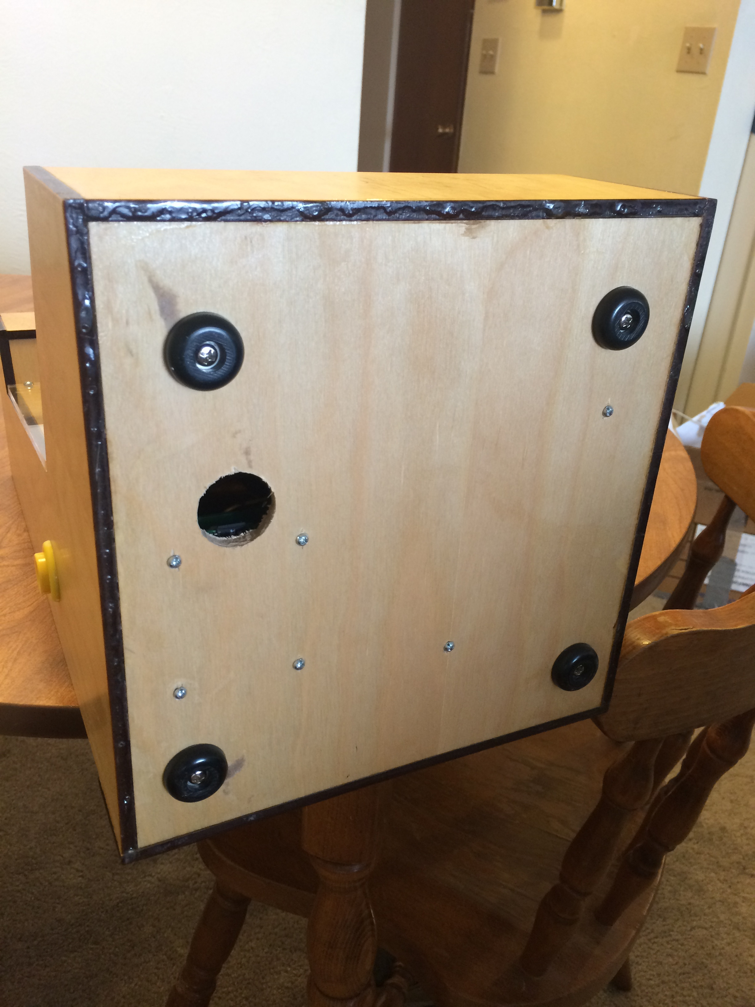 Here is the bottom. You can see my Hot Swap Bay aka a hole I drilled after the thought so I can access my SD card. That way I can take it out and back it up. I put a lot of work into getting the roms together, bios files and controller config etc etc. It would be devastating to have the card corrupt and have to start from scratch so back that shit up folks.
 -
28.
 Saw this while cruising the romset and it's an awful game.
 -
29.
 This can play classics, and it's finished...
 -
30.
 ... Good job Bentika!
- REPLAY GALLERY
-
- Guy Makes A Proper 4:3 Bartop Arcade Cabinet

Finished picture first, running the NES version of Galaga.
30/30
1/30


1 Comments